Source Four Mini Pen Pot
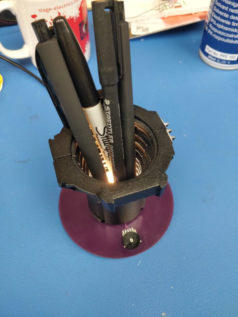
I came across the damaged lens tube of an ETC Source Four Mini in a scrap bin and knew I had to do something with it that retained some suggestion of its previous life. I quickly decided that it would make a good (or interesting) pen pot. It also was a good opportunity to design a PWM generator with discrete components and try the Würth Elektronik MagI³C-LDHM LED driver.
I wanted the PCB to form the base that kept the pen pot upright, so (almost) all of the components would need to be surface mount and fit within the footprint of the lens tube itself. I figured out a way of using the existing lens element holders inside the lens tube to support an array of warm white, high CRI LEDs to be the light source of the “fixture”; and a frosted acrylic disc leftover from another project conveniently fit above it to diffuse the light. I found a surface mount potentiometer with a large thumbwheel to make dimming easy. The whole thing is powered from USB 5V, readily available on my desk.
The construction of the elements means that the lens tube locks into the PCB base and is supported by a pair of standoffs between the PCB base and the LED array PCB; resulting in a clean yet robust assembly.
It feels like a waste of energy to have this lit whenever I’m at my desk so it is normally unplugged. But it is very satisfying to switch on every now and again to give my stationery a theatrical glow.
ETC Gadget Hub
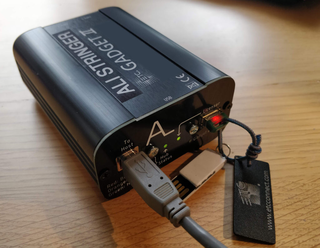
I own an ETC Nomad/Gadget kit that I use primarily for testing DMX devices. As a user of laptops with only 2 USB ports, I was consistently frustrated by either needing both USB ports to run Eos or finding a USB hub to use more USB devices at the same time. My solution: integrate a USB hub into the Gadget so that the license dongle could be connected via the same USB cable as the Gadget.
This was my first design involving USB and a 4 layer PCB so I selected an appropriate hub controller IC and drew up a generic 2 port USB hub first to verify the core functions before considering how it would interface with the Gadget. After spending a long time tracking down a problem that prevented the hub from enumerating (including a support ticket with the manufacturer), I tried swapping the host side USB data lines over and it suddenly started working.
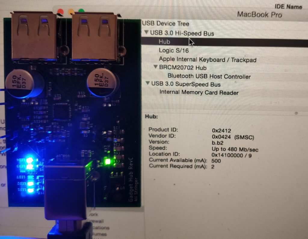
Alongside the electronic design, I wanted to find a way to make this modification easy and as minimally invasive to the Gadget as possible. I settled on desoldering the stock USB socket and screwing the hub PCB to the Gadget PCB using the shield pads of the USB connector I had just removed. Electrical connection was made by pogo pins, which took quite a bit of searching to find the right size that were big enough to make proper contact but small enough for the pin pitch.
Putting the generic hub design and mechanical/electrical interfacing together, I laid out a PCB that brought the upstream port and one of the downstream ports out to the user and connected the other downstream port to the Gadget’s USB pads. A set of custom end panels made room the new USB connector locations and passed the indicator LEDs through for easy viewing.
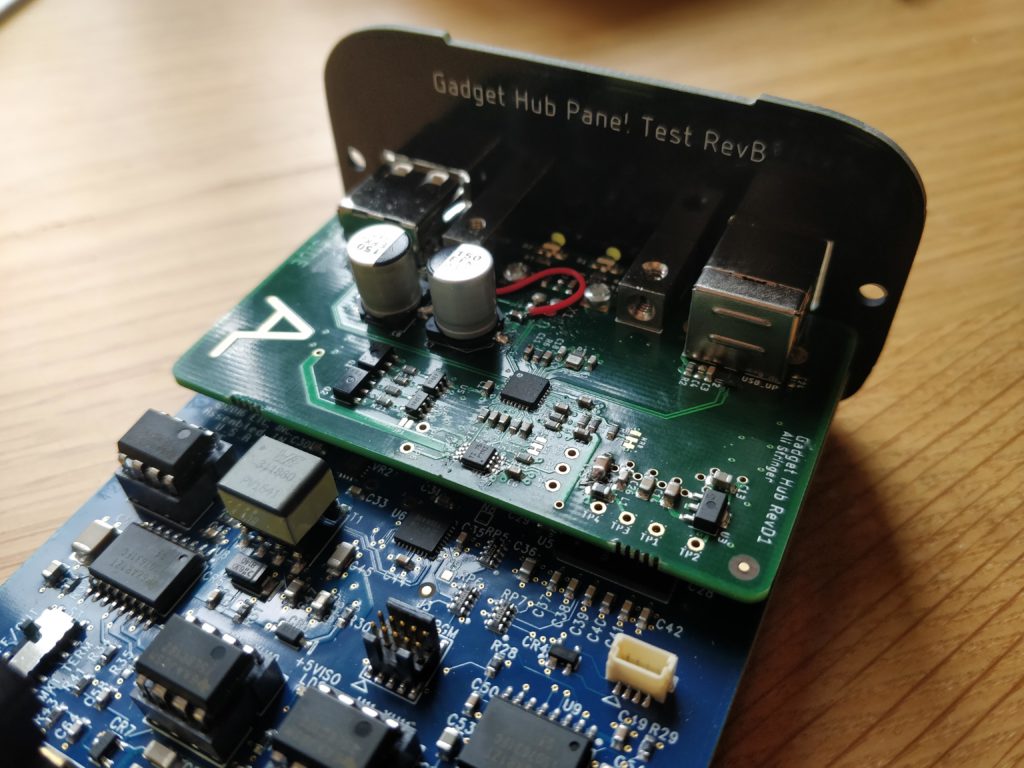
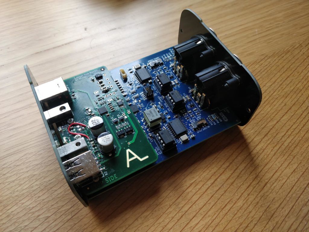
The photos above show the Gadget Hub installed onto a Gadget PCB. Since these photos were taken, I improved the design and added an optional USB socket location for the licenser dongle to be installed inside the enclosure to keep it with the Gadget.
QLab Remote
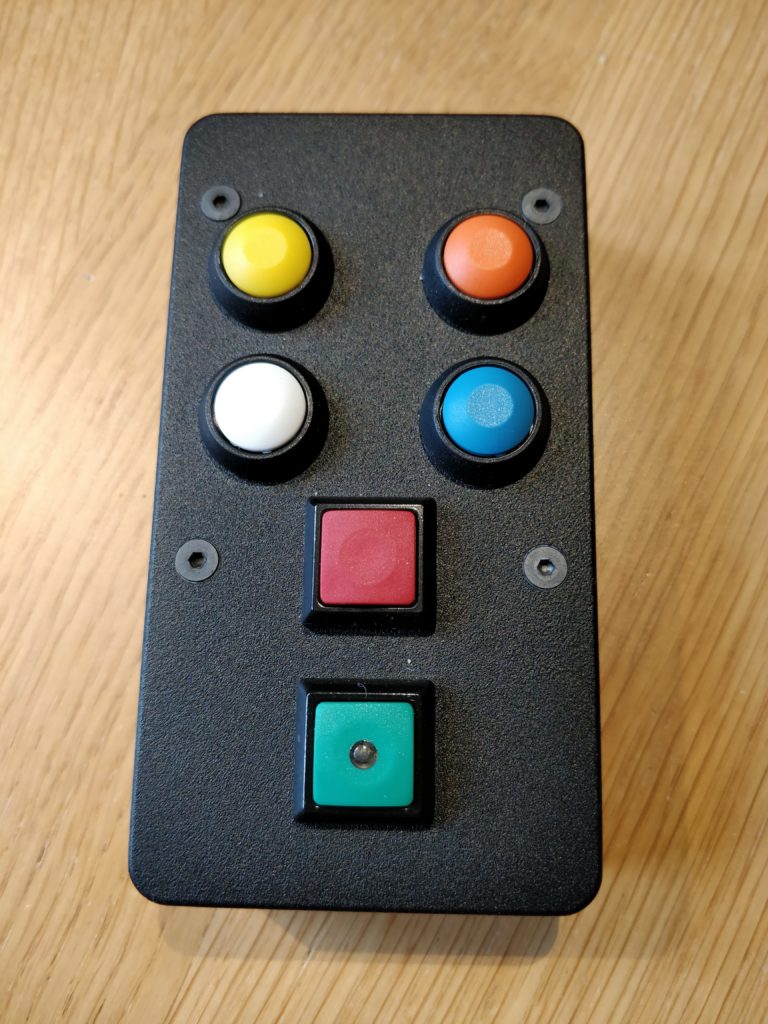
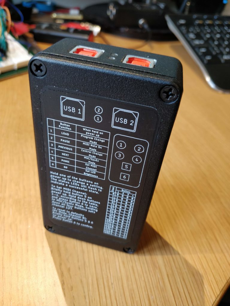
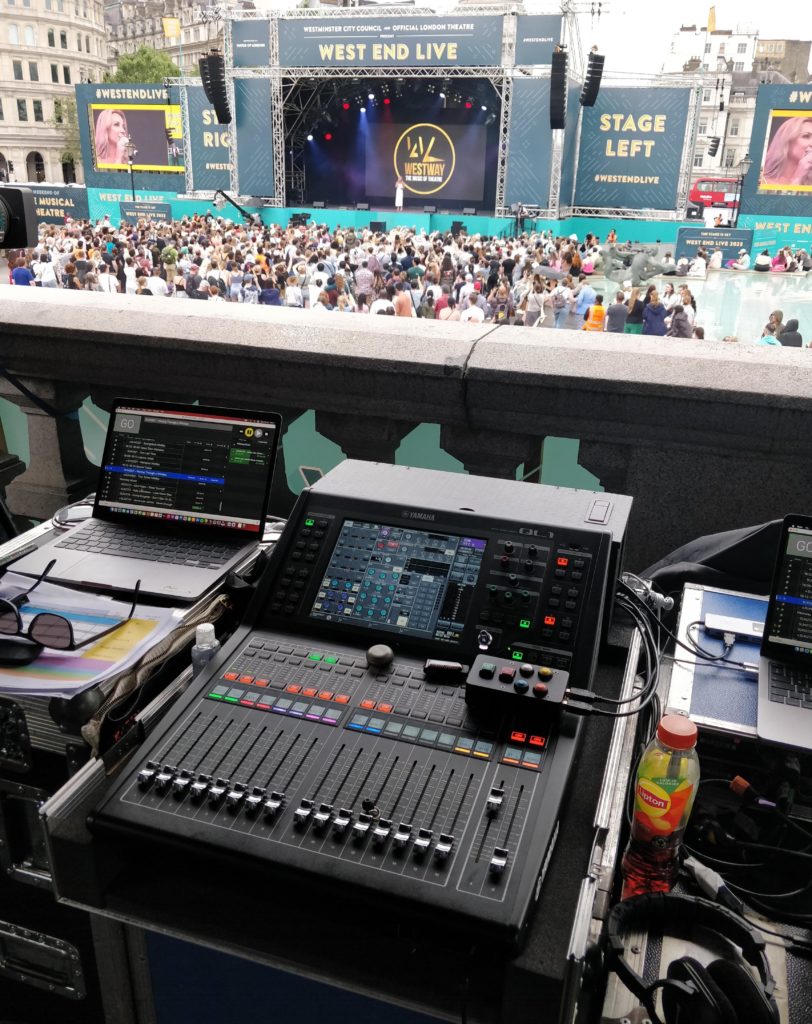
While commercially available dual output QLab remotes exist, I wanted one in a form factor I prefer (and an excuse to build one). Being a show control remote, it had to be designed to be robust and reliable. I based the design around the ATmega32U4 for its native USB support. Two of these microcontrollers live inside the remote, one for each QLab machine. They take the same debounced button inputs and convert the button presses to MIDI messages that are sent by USB to the host computer. All buttons are Apem; and the go button is illuminated for easy location in dark environments. The USB connectors are high retention connectors to prevent accidental disconnection.
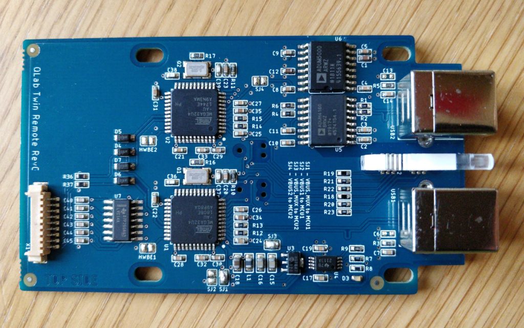
I wanted the remote to be as flexible as possible without having to reprogram the microcontrollers each time a setting needed to be changed. I use the buttons on power up to select a different mode, channel, go indicator brightness or default settings.
Fringe Venue Latecomer System
To solve the problem of venue technicians disturbing performances by answering radio calls from front of house staff about latecomers, I was asked to build a simple system that could be used within fringe venues to allow the technician inside the venue to give a response without using their radios.
A “cue light” style system seemed the most appropriate solution for its familiarity and simplicity. At the control position inside the venue, a controller with buttons for each response would light up the relevant indicator on an outstation installed at the front of house position. Cat5 cable, terminated with 3 pin XLR, was chosen for permanent cable runs between the venues and front of house positions. For the festival, the controller and outstations are plugged in and tested; after the festival, they are removed and stored while the cable remains in place.
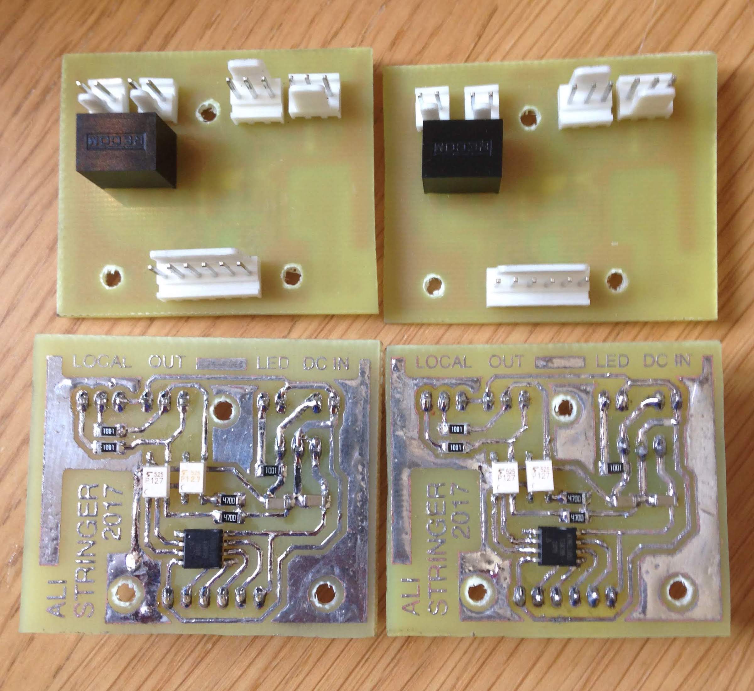
I designed a simple home-brew PCB, based around an ATtiny85 microcontroller that reads the buttons on the controller and drives the indicators in the outstations accordingly. An indicator on the controller mimics the output to show the venue technician what state the remote station is in.
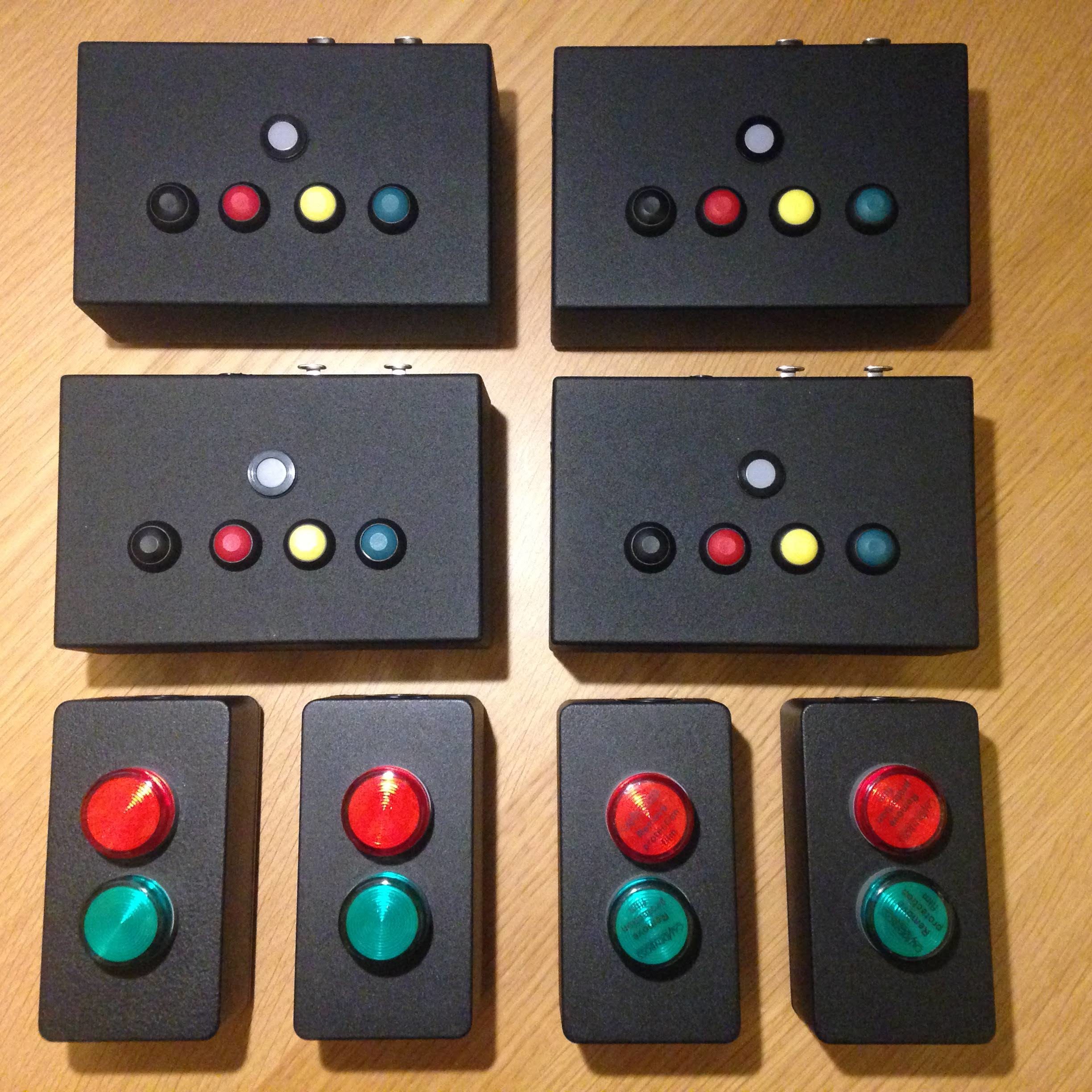
Below is a short video demonstrating the functions of the system. I put two outputs on each controller, in case multiple outstations were required in the future.